Various changes have been made to more than just bb5.c -- don't just blindly try to reuse your old code.
In this project, you're going to make the code generated by the previous projects into gate-level hardware. There are more than a few issues in doing that, but we'll get you there. Will it be good gate-level hardware? Well, not really, but it's pretty impressive anyway.
Fundamentally, basic blocks are combinatorial circuits. There are just a couple of major exceptions to that:
Then there's the whole matter of building a state machine around the basic blocks. In truth, the circuitry for all blocks coexists, so we can actually optimize the circuit as a single entity -- which even includes the computation of the next state. The compiler creates a STATE variable and the code to update it, and to ensure that other variables are only written with the correct values in the correct states. Scary, eh?
The new infrastructure for your project took me quite a while to create and debug, even after building a version for last year. Unlike any other systems I am aware of, this literally takes in code in a C dialect (which is by now somewhat familiar to you) and then outputs an optimized, complete, gate-level state machine implementing it. It's not too uncommon to see a basic block translated into gates, and tools for HDLs (e.g., Verilog) generally translate code into interconnections between fixed logic blocks to implement a state machine, but this does everything at the gate level.
Fortunately for you, the code that does all that work is given to you. All that you need to do for this project is to modify the bb3.tgz source code so that it uses only a single type of gate for all designs. The single type can be any of:
Because NAND and NOR are binary operators, they are easier to implement than ITE for the code infrastructure. In fact, there are already operator types defined for them and the formatted output also knows about them... which is not the case for ITEs. Nearly everything that you would want to do only requires editing bb6.c, which contains almost everything dealing with the bit-level representations of busses and gates.
If you are a graduate student, you must add a command-line option to select between either of two single-gate types. The obvious place to add the command-line option processing is bb1.c, and you can use something like -a for NAND, -o for NOR, or -m for muliplexor. It's up to you. I don't care which two types of single gate you implement.
In your implementor's notes, you are also expected to comment on how restricting the gate type affects the circuit complexity. If you're a grad student, you have two single types to comment on.
Basically, bbgates is an enhanced version of the same compiler you've been playing with all semester. However, it now has a somewhat different command line, requiring at least one option to specify what type of output to generate (always taking input from stdin and writing output to stdout):
As we discussed in class, there are a two important restrictions for any of the outputs that generate gate-level designs:
Aside from that, it's the same language you've been dealing with all along.
The Makefile includes support for make test, which tries a simple test case. The input file, testg.c, is about as simple a test case as is interesting:
int a, b, c;

f()
{
	b = 3;
	a = 10;
	while (a > b) {
		a = a - 1;
	}
	c = a - b;
}
So, what does that generate?
The sequential output is just text (in gates.seq) that looks like:
0	lab(0)
1	const(0)
2	const(3)
3	st(b{1,1}, 2)
4	const(10)
5	st(a{1,1}, 4)
6	lab(1)
7	const(0)
8	ld(a{1,1})
9	ld(b{1,1})
10	gt(8, 9)
11	sel(10, 3, 2)
12	lab(3)
13	const(0)
14	ld(a{1,1})
15	const(1)
16	sub(14, 15)
17	st(a{1,1}, 16)
18	sel(-1, 1, 1)
19	lab(2)
20	const(0)
21	ld(a{1,1})
22	ld(b{1,1})
23	sub(21, 22)
24	st(c{1,1}, 23)
25	lab(4)
Notice that the final label is actually significant in that reaching that label is what terminates the program.
The gate-level output, generated using the -g command line option, outputs somewhat human-readable text (in gates) at the gate level:
G2 = XOR(_1, STATE_0_0_7)
G3 = XOR(_1, STATE_0_0_6)
G4 = AND(G2, G3)
G5 = XOR(_1, STATE_0_0_5)
G6 = AND(G4, G5)
G7 = XOR(_1, STATE_0_0_4)
G8 = AND(G6, G7)
G9 = XOR(_1, STATE_0_0_3)
G10 = AND(G8, G9)
G11 = XOR(_1, STATE_0_0_2)
G12 = AND(G10, G11)
G13 = XOR(_1, STATE_0_0_1)
G14 = AND(G12, G13)
G15 = XOR(_1, STATE_0_0_0)
G16 = AND(G14, G15)
G17 = XOR(_1, G16)
G18 = AND(G17, b_1_1_0)
G19 = OR(G16, G18)
G20 = AND(G17, b_1_1_1)
G21 = OR(G16, G20)
G22 = AND(G17, b_1_1_2)
G23 = AND(G17, b_1_1_3)
G24 = AND(G17, b_1_1_4)
G25 = AND(G17, b_1_1_5)
G26 = AND(G17, b_1_1_6)
G27 = AND(G17, b_1_1_7)
G28 = AND(G17, a_1_1_0)
G29 = AND(G17, a_1_1_1)
G30 = OR(G16, G29)
G31 = AND(G17, a_1_1_2)
G32 = AND(G17, a_1_1_3)
G33 = OR(G16, G32)
G34 = AND(G17, a_1_1_4)
G35 = AND(G17, a_1_1_5)
G36 = AND(G17, a_1_1_6)
G37 = AND(G17, a_1_1_7)
G38 = AND(G14, STATE_0_0_0)
G39 = XOR(_1, a_1_1_0)
G40 = XOR(_1, a_1_1_1)
G41 = XOR(_1, a_1_1_2)
G42 = XOR(_1, a_1_1_3)
G43 = XOR(_1, a_1_1_4)
G44 = XOR(_1, a_1_1_5)
G45 = XOR(_1, a_1_1_6)
G46 = XOR(_1, a_1_1_7)
G47 = XOR(G39, b_1_1_0)
G48 = AND(G39, b_1_1_0)
G49 = OR(G47, G48)
G50 = XOR(G40, b_1_1_1)
G51 = AND(G40, b_1_1_1)
G52 = AND(G49, G50)
G53 = OR(G51, G52)
G54 = XOR(G41, b_1_1_2)
G55 = AND(G41, b_1_1_2)
G56 = AND(G53, G54)
G57 = OR(G55, G56)
G58 = XOR(G42, b_1_1_3)
G59 = AND(G42, b_1_1_3)
G60 = AND(G57, G58)
G61 = OR(G59, G60)
G62 = XOR(G43, b_1_1_4)
G63 = AND(G43, b_1_1_4)
G64 = AND(G61, G62)
G65 = OR(G63, G64)
G66 = XOR(G44, b_1_1_5)
G67 = AND(G44, b_1_1_5)
G68 = AND(G65, G66)
G69 = OR(G67, G68)
G70 = XOR(G45, b_1_1_6)
G71 = AND(G45, b_1_1_6)
G72 = AND(G69, G70)
G73 = OR(G71, G72)
G74 = XOR(G46, b_1_1_7)
G75 = XOR(G73, G74)
G76 = XOR(_1, G38)
G77 = AND(G16, G76)
G78 = AND(G38, G75)
G79 = OR(G77, G78)
G80 = AND(G12, STATE_0_0_1)
G81 = AND(G80, STATE_0_0_0)
G82 = XOR(_1, _1)
G83 = XOR(_0, _1)
G84 = XOR(G82, a_1_1_0)
G85 = XOR(_1, G84)
G86 = AND(G82, a_1_1_0)
G87 = OR(G84, G86)
G88 = XOR(G83, a_1_1_1)
G89 = XOR(G87, G88)
G90 = AND(G83, a_1_1_1)
G91 = AND(G87, G88)
G92 = OR(G90, G91)
G93 = XOR(G83, a_1_1_2)
G94 = XOR(G92, G93)
G95 = AND(G83, a_1_1_2)
G96 = AND(G92, G93)
G97 = OR(G95, G96)
G98 = XOR(G83, a_1_1_3)
G99 = XOR(G97, G98)
G100 = AND(G83, a_1_1_3)
G101 = AND(G97, G98)
G102 = OR(G100, G101)
G103 = XOR(G83, a_1_1_4)
G104 = XOR(G102, G103)
G105 = AND(G83, a_1_1_4)
G106 = AND(G102, G103)
G107 = OR(G105, G106)
G108 = XOR(G83, a_1_1_5)
G109 = XOR(G107, G108)
G110 = AND(G83, a_1_1_5)
G111 = AND(G107, G108)
G112 = OR(G110, G111)
G113 = XOR(G83, a_1_1_6)
G114 = XOR(G112, G113)
G115 = AND(G83, a_1_1_6)
G116 = AND(G112, G113)
G117 = OR(G115, G116)
G118 = XOR(G83, a_1_1_7)
G119 = XOR(G117, G118)
G120 = XOR(_1, G81)
G121 = AND(G28, G120)
G122 = AND(G81, G85)
G123 = OR(G121, G122)
G124 = AND(G30, G120)
G125 = AND(G81, G89)
G126 = OR(G124, G125)
G127 = AND(G31, G120)
G128 = AND(G81, G94)
G129 = OR(G127, G128)
G130 = AND(G33, G120)
G131 = AND(G81, G99)
G132 = OR(G130, G131)
G133 = AND(G34, G120)
G134 = AND(G81, G104)
G135 = OR(G133, G134)
G136 = AND(G35, G120)
G137 = AND(G81, G109)
G138 = OR(G136, G137)
G139 = AND(G36, G120)
G140 = AND(G81, G114)
G141 = OR(G139, G140)
G142 = AND(G37, G120)
G143 = AND(G81, G119)
G144 = OR(G142, G143)
G145 = AND(G79, G120)
G146 = OR(G81, G145)
G147 = AND(G38, G120)
G148 = AND(G15, G80)
G149 = XOR(_1, b_1_1_0)
G150 = XOR(_1, b_1_1_1)
G151 = XOR(_1, b_1_1_2)
G152 = XOR(_1, b_1_1_3)
G153 = XOR(_1, b_1_1_4)
G154 = XOR(_1, b_1_1_5)
G155 = XOR(_1, b_1_1_6)
G156 = XOR(_1, b_1_1_7)
G157 = XOR(G149, a_1_1_0)
G158 = XOR(_1, G157)
G159 = AND(G149, a_1_1_0)
G160 = OR(G157, G159)
G161 = XOR(G150, a_1_1_1)
G162 = XOR(G160, G161)
G163 = AND(G150, a_1_1_1)
G164 = AND(G160, G161)
G165 = OR(G163, G164)
G166 = XOR(G151, a_1_1_2)
G167 = XOR(G165, G166)
G168 = AND(G151, a_1_1_2)
G169 = AND(G165, G166)
G170 = OR(G168, G169)
G171 = XOR(G152, a_1_1_3)
G172 = XOR(G170, G171)
G173 = AND(G152, a_1_1_3)
G174 = AND(G170, G171)
G175 = OR(G173, G174)
G176 = XOR(G153, a_1_1_4)
G177 = XOR(G175, G176)
G178 = AND(G153, a_1_1_4)
G179 = AND(G175, G176)
G180 = OR(G178, G179)
G181 = XOR(G154, a_1_1_5)
G182 = XOR(G180, G181)
G183 = AND(G154, a_1_1_5)
G184 = AND(G180, G181)
G185 = OR(G183, G184)
G186 = XOR(G155, a_1_1_6)
G187 = XOR(G185, G186)
G188 = AND(G155, a_1_1_6)
G189 = AND(G185, G186)
G190 = OR(G188, G189)
G191 = XOR(G156, a_1_1_7)
G192 = XOR(G190, G191)
G193 = XOR(_1, G148)
G194 = AND(G193, c_1_1_0)
G195 = AND(G148, G158)
G196 = OR(G194, G195)
G197 = AND(G193, c_1_1_1)
G198 = AND(G148, G162)
G199 = OR(G197, G198)
G200 = AND(G193, c_1_1_2)
G201 = AND(G148, G167)
G202 = OR(G200, G201)
G203 = AND(G193, c_1_1_3)
G204 = AND(G148, G172)
G205 = OR(G203, G204)
G206 = AND(G193, c_1_1_4)
G207 = AND(G148, G177)
G208 = OR(G206, G207)
G209 = AND(G193, c_1_1_5)
G210 = AND(G148, G182)
G211 = OR(G209, G210)
G212 = AND(G193, c_1_1_6)
G213 = AND(G148, G187)
G214 = OR(G212, G213)
G215 = AND(G193, c_1_1_7)
G216 = AND(G148, G192)
G217 = OR(G215, G216)
G218 = AND(G146, G193)
G219 = AND(G147, G193)
_a_1_1_0 = G123
_a_1_1_1 = G126
_a_1_1_2 = G129
_a_1_1_3 = G132
_a_1_1_4 = G135
_a_1_1_5 = G138
_a_1_1_6 = G141
_a_1_1_7 = G144
_b_1_1_0 = G19
_b_1_1_1 = G21
_b_1_1_2 = G22
_b_1_1_3 = G23
_b_1_1_4 = G24
_b_1_1_5 = G25
_b_1_1_6 = G26
_b_1_1_7 = G27
_c_1_1_0 = G196
_c_1_1_1 = G199
_c_1_1_2 = G202
_c_1_1_3 = G205
_c_1_1_4 = G208
_c_1_1_5 = G211
_c_1_1_6 = G214
_c_1_1_7 = G217
_STATE_0_0_0 = G218
_STATE_0_0_1 = G219
_STATE_0_0_2 = G148
_STATE_0_0_3 = _0
_STATE_0_0_4 = _0
_STATE_0_0_5 = _0
_STATE_0_0_6 = _0
_STATE_0_0_7 = _0
Notice that each line deals only with a single bit of data. Also, each bit of each variable appears as two nodes: one read at the start of the clock cycle and a second, marked with an _ prefix, which is written at the end of the clock cycle.
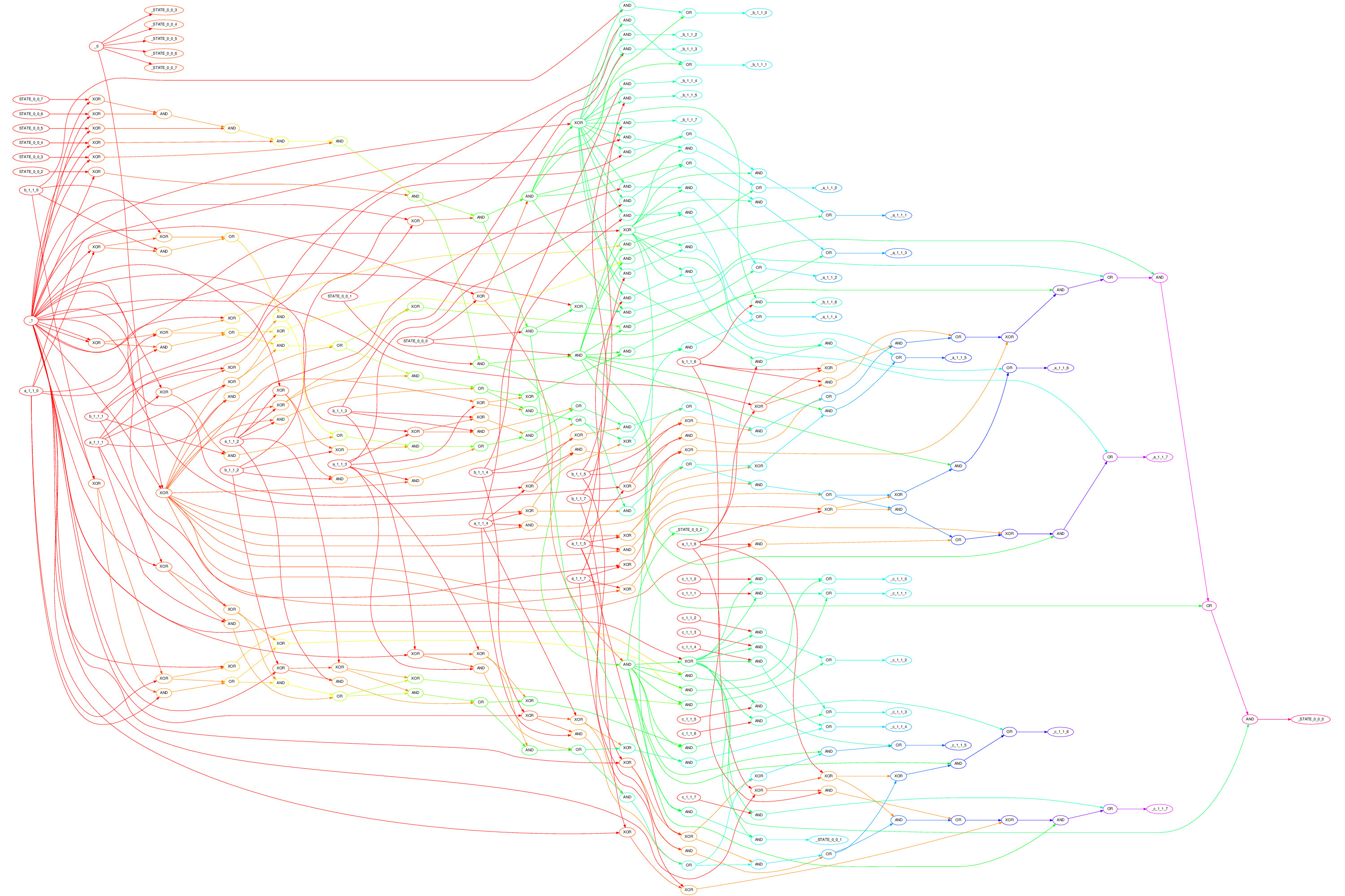
The textual gate-level output is difficult to understand because it is so many lines. Thus, bbgates can also generate a graphical gate-level representation. It doesn't do that directly, but creates a Graphviz description suitable for processing by Dot. Rather than looking at the Dot file (in gates.dot), here's what it looks like as a PNG graphic:
This is not quite standard Verilog code because $dumpfile is missing a file name -- but that's the only change needed to be able to run it through this HTML-form-interfaced Verilog compiler/simulator. Here's the Verilog code (in gates.v):
module statemachine(halt, clk);
output halt;
input clk;
reg [7:0] a_1_1;
reg [7:0] b_1_1;
reg [7:0] c_1_1;
reg [7:0] STATE_0_0 = 0;
wire [217:0] w;

xor(w[0], 1, STATE_0_0[7]);
xor(w[1], 1, STATE_0_0[6]);
and(w[2], w[0], w[1]);
xor(w[3], 1, STATE_0_0[5]);
and(w[4], w[2], w[3]);
xor(w[5], 1, STATE_0_0[4]);
and(w[6], w[4], w[5]);
xor(w[7], 1, STATE_0_0[3]);
and(w[8], w[6], w[7]);
xor(w[9], 1, STATE_0_0[2]);
and(w[10], w[8], w[9]);
xor(w[11], 1, STATE_0_0[1]);
and(w[12], w[10], w[11]);
xor(w[13], 1, STATE_0_0[0]);
and(w[14], w[12], w[13]);
xor(w[15], 1, w[14]);
and(w[16], w[15], b_1_1[0]);
or(w[17], w[14], w[16]);
and(w[18], w[15], b_1_1[1]);
or(w[19], w[14], w[18]);
and(w[20], w[15], b_1_1[2]);
and(w[21], w[15], b_1_1[3]);
and(w[22], w[15], b_1_1[4]);
and(w[23], w[15], b_1_1[5]);
and(w[24], w[15], b_1_1[6]);
and(w[25], w[15], b_1_1[7]);
and(w[26], w[15], a_1_1[0]);
and(w[27], w[15], a_1_1[1]);
or(w[28], w[14], w[27]);
and(w[29], w[15], a_1_1[2]);
and(w[30], w[15], a_1_1[3]);
or(w[31], w[14], w[30]);
and(w[32], w[15], a_1_1[4]);
and(w[33], w[15], a_1_1[5]);
and(w[34], w[15], a_1_1[6]);
and(w[35], w[15], a_1_1[7]);
and(w[36], w[12], STATE_0_0[0]);
xor(w[37], 1, a_1_1[0]);
xor(w[38], 1, a_1_1[1]);
xor(w[39], 1, a_1_1[2]);
xor(w[40], 1, a_1_1[3]);
xor(w[41], 1, a_1_1[4]);
xor(w[42], 1, a_1_1[5]);
xor(w[43], 1, a_1_1[6]);
xor(w[44], 1, a_1_1[7]);
xor(w[45], w[37], b_1_1[0]);
and(w[46], w[37], b_1_1[0]);
or(w[47], w[45], w[46]);
xor(w[48], w[38], b_1_1[1]);
and(w[49], w[38], b_1_1[1]);
and(w[50], w[47], w[48]);
or(w[51], w[49], w[50]);
xor(w[52], w[39], b_1_1[2]);
and(w[53], w[39], b_1_1[2]);
and(w[54], w[51], w[52]);
or(w[55], w[53], w[54]);
xor(w[56], w[40], b_1_1[3]);
and(w[57], w[40], b_1_1[3]);
and(w[58], w[55], w[56]);
or(w[59], w[57], w[58]);
xor(w[60], w[41], b_1_1[4]);
and(w[61], w[41], b_1_1[4]);
and(w[62], w[59], w[60]);
or(w[63], w[61], w[62]);
xor(w[64], w[42], b_1_1[5]);
and(w[65], w[42], b_1_1[5]);
and(w[66], w[63], w[64]);
or(w[67], w[65], w[66]);
xor(w[68], w[43], b_1_1[6]);
and(w[69], w[43], b_1_1[6]);
and(w[70], w[67], w[68]);
or(w[71], w[69], w[70]);
xor(w[72], w[44], b_1_1[7]);
xor(w[73], w[71], w[72]);
xor(w[74], 1, w[36]);
and(w[75], w[14], w[74]);
and(w[76], w[36], w[73]);
or(w[77], w[75], w[76]);
and(w[78], w[10], STATE_0_0[1]);
and(w[79], w[78], STATE_0_0[0]);
xor(w[80], 1, 1);
xor(w[81], 0, 1);
xor(w[82], w[80], a_1_1[0]);
xor(w[83], 1, w[82]);
and(w[84], w[80], a_1_1[0]);
or(w[85], w[82], w[84]);
xor(w[86], w[81], a_1_1[1]);
xor(w[87], w[85], w[86]);
and(w[88], w[81], a_1_1[1]);
and(w[89], w[85], w[86]);
or(w[90], w[88], w[89]);
xor(w[91], w[81], a_1_1[2]);
xor(w[92], w[90], w[91]);
and(w[93], w[81], a_1_1[2]);
and(w[94], w[90], w[91]);
or(w[95], w[93], w[94]);
xor(w[96], w[81], a_1_1[3]);
xor(w[97], w[95], w[96]);
and(w[98], w[81], a_1_1[3]);
and(w[99], w[95], w[96]);
or(w[100], w[98], w[99]);
xor(w[101], w[81], a_1_1[4]);
xor(w[102], w[100], w[101]);
and(w[103], w[81], a_1_1[4]);
and(w[104], w[100], w[101]);
or(w[105], w[103], w[104]);
xor(w[106], w[81], a_1_1[5]);
xor(w[107], w[105], w[106]);
and(w[108], w[81], a_1_1[5]);
and(w[109], w[105], w[106]);
or(w[110], w[108], w[109]);
xor(w[111], w[81], a_1_1[6]);
xor(w[112], w[110], w[111]);
and(w[113], w[81], a_1_1[6]);
and(w[114], w[110], w[111]);
or(w[115], w[113], w[114]);
xor(w[116], w[81], a_1_1[7]);
xor(w[117], w[115], w[116]);
xor(w[118], 1, w[79]);
and(w[119], w[26], w[118]);
and(w[120], w[79], w[83]);
or(w[121], w[119], w[120]);
and(w[122], w[28], w[118]);
and(w[123], w[79], w[87]);
or(w[124], w[122], w[123]);
and(w[125], w[29], w[118]);
and(w[126], w[79], w[92]);
or(w[127], w[125], w[126]);
and(w[128], w[31], w[118]);
and(w[129], w[79], w[97]);
or(w[130], w[128], w[129]);
and(w[131], w[32], w[118]);
and(w[132], w[79], w[102]);
or(w[133], w[131], w[132]);
and(w[134], w[33], w[118]);
and(w[135], w[79], w[107]);
or(w[136], w[134], w[135]);
and(w[137], w[34], w[118]);
and(w[138], w[79], w[112]);
or(w[139], w[137], w[138]);
and(w[140], w[35], w[118]);
and(w[141], w[79], w[117]);
or(w[142], w[140], w[141]);
and(w[143], w[77], w[118]);
or(w[144], w[79], w[143]);
and(w[145], w[36], w[118]);
and(w[146], w[13], w[78]);
xor(w[147], 1, b_1_1[0]);
xor(w[148], 1, b_1_1[1]);
xor(w[149], 1, b_1_1[2]);
xor(w[150], 1, b_1_1[3]);
xor(w[151], 1, b_1_1[4]);
xor(w[152], 1, b_1_1[5]);
xor(w[153], 1, b_1_1[6]);
xor(w[154], 1, b_1_1[7]);
xor(w[155], w[147], a_1_1[0]);
xor(w[156], 1, w[155]);
and(w[157], w[147], a_1_1[0]);
or(w[158], w[155], w[157]);
xor(w[159], w[148], a_1_1[1]);
xor(w[160], w[158], w[159]);
and(w[161], w[148], a_1_1[1]);
and(w[162], w[158], w[159]);
or(w[163], w[161], w[162]);
xor(w[164], w[149], a_1_1[2]);
xor(w[165], w[163], w[164]);
and(w[166], w[149], a_1_1[2]);
and(w[167], w[163], w[164]);
or(w[168], w[166], w[167]);
xor(w[169], w[150], a_1_1[3]);
xor(w[170], w[168], w[169]);
and(w[171], w[150], a_1_1[3]);
and(w[172], w[168], w[169]);
or(w[173], w[171], w[172]);
xor(w[174], w[151], a_1_1[4]);
xor(w[175], w[173], w[174]);
and(w[176], w[151], a_1_1[4]);
and(w[177], w[173], w[174]);
or(w[178], w[176], w[177]);
xor(w[179], w[152], a_1_1[5]);
xor(w[180], w[178], w[179]);
and(w[181], w[152], a_1_1[5]);
and(w[182], w[178], w[179]);
or(w[183], w[181], w[182]);
xor(w[184], w[153], a_1_1[6]);
xor(w[185], w[183], w[184]);
and(w[186], w[153], a_1_1[6]);
and(w[187], w[183], w[184]);
or(w[188], w[186], w[187]);
xor(w[189], w[154], a_1_1[7]);
xor(w[190], w[188], w[189]);
xor(w[191], 1, w[146]);
and(w[192], w[191], c_1_1[0]);
and(w[193], w[146], w[156]);
or(w[194], w[192], w[193]);
and(w[195], w[191], c_1_1[1]);
and(w[196], w[146], w[160]);
or(w[197], w[195], w[196]);
and(w[198], w[191], c_1_1[2]);
and(w[199], w[146], w[165]);
or(w[200], w[198], w[199]);
and(w[201], w[191], c_1_1[3]);
and(w[202], w[146], w[170]);
or(w[203], w[201], w[202]);
and(w[204], w[191], c_1_1[4]);
and(w[205], w[146], w[175]);
or(w[206], w[204], w[205]);
and(w[207], w[191], c_1_1[5]);
and(w[208], w[146], w[180]);
or(w[209], w[207], w[208]);
and(w[210], w[191], c_1_1[6]);
and(w[211], w[146], w[185]);
or(w[212], w[210], w[211]);
and(w[213], w[191], c_1_1[7]);
and(w[214], w[146], w[190]);
or(w[215], w[213], w[214]);
and(w[216], w[144], w[191]);
and(w[217], w[145], w[191]);
assign halt = (STATE_0_0 == 4);
always @(posedge clk) if (!halt) begin
	a_1_1[0] <= w[121];
	a_1_1[1] <= w[124];
	a_1_1[2] <= w[127];
	a_1_1[3] <= w[130];
	a_1_1[4] <= w[133];
	a_1_1[5] <= w[136];
	a_1_1[6] <= w[139];
	a_1_1[7] <= w[142];
	b_1_1[0] <= w[17];
	b_1_1[1] <= w[19];
	b_1_1[2] <= w[20];
	b_1_1[3] <= w[21];
	b_1_1[4] <= w[22];
	b_1_1[5] <= w[23];
	b_1_1[6] <= w[24];
	b_1_1[7] <= w[25];
	c_1_1[0] <= w[194];
	c_1_1[1] <= w[197];
	c_1_1[2] <= w[200];
	c_1_1[3] <= w[203];
	c_1_1[4] <= w[206];
	c_1_1[5] <= w[209];
	c_1_1[6] <= w[212];
	c_1_1[7] <= w[215];
	STATE_0_0[0] <= w[216];
	STATE_0_0[1] <= w[217];
	STATE_0_0[2] <= w[146];
	STATE_0_0[3] <= 0;
	STATE_0_0[4] <= 0;
	STATE_0_0[5] <= 0;
	STATE_0_0[6] <= 0;
	STATE_0_0[7] <= 0;
end
endmodule

module testbench;
wire halt;
reg clk = 0;
statemachine m(halt, clk);
initial begin
	$dumpfile;
	$dumpvars(1,
m.a_1_1,
m.b_1_1,
m.c_1_1,
m.STATE_0_0);
	while (!halt) begin
		#1 clk <= !clk;
	end
	$finish;
end
endmodule
Notice the sneaky use of `define, which you should appreciate because it makes NAND and NOR gates take an identical representation. In any case, running that through the Verilog simulator generates a pretty big HTML response, which includes:
Trace Browser For VCD Generated By vvp Simulation

   $time     a_1_1    b_1_1    c_1_1 STATE_0_0
       0: xxxxxxxx xxxxxxxx xxxxxxxx  00000000
       1: 00001010 00000011 xxxxxxxx  00000001
       3: 00001010 00000011 xxxxxxxx  00000011
       5: 00001001 00000011 xxxxxxxx  00000001
       7: 00001001 00000011 xxxxxxxx  00000011
       9: 00001000 00000011 xxxxxxxx  00000001
      11: 00001000 00000011 xxxxxxxx  00000011
      13: 00000111 00000011 xxxxxxxx  00000001
      15: 00000111 00000011 xxxxxxxx  00000011
      17: 00000110 00000011 xxxxxxxx  00000001
      19: 00000110 00000011 xxxxxxxx  00000011
      21: 00000101 00000011 xxxxxxxx  00000001
      23: 00000101 00000011 xxxxxxxx  00000011
      25: 00000100 00000011 xxxxxxxx  00000001
      27: 00000100 00000011 xxxxxxxx  00000011
      29: 00000011 00000011 xxxxxxxx  00000001
      31: 00000011 00000011 xxxxxxxx  00000010
      33: 00000011 00000011 00000000  00000100
That's pretty self-explanatory, except for the $time. It takes two simulator time units per clock cycle, one up and one down, with the state machine triggered on positive edges... which is why updates happen only on odd simulation time units.
The final exam is Thursday, May 3, at 1:00PM. Submit your project before then. As usual, you may submit as many times as you wish, but only the last submission that you make before the final deadline will be counted toward your course grade.
Note that you can ensure that you get at least half credit for this project by simply submitting a tar of an "implementor's notes" document explaining that your project doesn't work because you have not done it yet. Given that, perhaps you should start by immediately making and submitting your implementor's notes document? (I would!)
For each project, you will be submitting a tarball (i.e., a file with the name ending in .tar or .tgz) that contains all things relevant to your work on the project. Minimally, each project tarball includes the source code for the project and a semi-formal "implementors notes" document as a PDF named notes.pdf. It also may include test cases, sample output, a make file, etc., but should not include any files that are built by your Makefile (e.g., no binary executables). Make it very clear in your implementor's notes exactly what you did and also be sure to comment on how much constraining the gate type changed the circuit complexity.
Submit your tarball below. The file can be either an ordinary .tar file created using tar cvf file.tar yourprojectfiles or a compressed .tgz file file created using tar zcvf file.tgz yourprojectfiles. Be careful about using * as a shorthand in listing yourprojectfiles on the command line, because if the output tar file is listed in the expansion, the result can be an infinite file (which is not ok).