
Assignment 3: A SIK Pipeline
In this project, your team is going to build a pipelined
implementation of SIK, the little instruction set design you
built multi-cycle implementation of in Assignment 2.
Pipelined Stack Code?
SIK is a stack machine. That is not the kind of model you expect
to be pipelining, because there are very frequenlty dependences
between adjacent stack instructions thanks to everything
operating on the top of the stack. In fact, the changes to the
stack pointer itself are effectively serializing dependences!
So, how are we going to get any parallelism out of this?
-
The dependences on stack pointer updates become irrelevant to
the pipeline if they happen immediately after fetching an
instruction. Why? Well, stack instruction sets generally don't
change the stack pointer by unpredictable amounts late in the
pipeline. For example, Add always bumps the stack
pointer by +1 no matter what the values being added are. The
only suspect instruction in SIK is Pop, but the
constant that the stack pointer is being adjusted by is
built-into the instruction, so even it is available immediately
after instruction fetch. Thus, the stack pointer isn't accessed
from all stages, but rather the instructions that need it can
effectively carry a copy of the value they need with them.
-
There are 256 registers used to implement the stack. Thus, the
first step is to stop thinking of the stack as a stack, but
rather as a bunch of registers. This is not difficult. As soon
as a stack instruction is fetched, you can (and probably should)
convert it into a register-to-register operation. However, this
probably should take a clock cycle (pipe stage) because the
register numbers are generally derived as offsets from the
register number the stack pointer contains... so there is an
adder.
-
Dependences on registers are dependences on registers. Your
stack code transformed to work on registers still needs to have
all the usual checks for dependences on register use between
stages. You will still need to implement either interlock or
value forwarding.
-
Because stack instructions tend to work on the top of the stack
values, it is common that you'll get pipeline bubbles. Lots of
pipeline bubbles. However, you're going to get around that the
same way Intel got around instruction scheduling in their
processors. Rather than resorting to out-of-order execution,
your implementation will simply be multithreaded.
Multithreading means that there is more than one
virtual processor in your processor, and the hardware
itself directly implements timesharing at the single-clock-cycle
level. That probably sounds nasty, but it's really easy to do
Intel-style two-way hyperthreading:
-
You'll need two copies of all the registers: pc, stack pointer,
... the entire register file. Yup; you'll have 512 registers instead of 256.
That's basically a nine-bit register number with the top bit
saying which thread the register is associated with. Think of
everything as a 2-element array of all the registers you would
have in a single-thread processor. The cool thing is that
dependences can only happen between references in the same
thread, so alternating between threads each clock cycle ensures
there will never be a dependence between adjacent pipe stages.
-
You will be running two programs at once. This means not all
stage contents are affected by things like a delay in a
conditional branch (JumpF or JumpT) -- only
the thread that executes such an instruction is affected by how
that gets resolved. For example, if you speculatively execute an
instruction and find that you guessed wrong and that instruction
shouldn't be executed, you would convert it into a NOP; however,
the instructions in other stages that are from a different
thread shouldn't become NOPs. This also brings up the point
that if you stall one thread, that doesn't necessarily mean the
other thread must stall. You could even let the one active
thread schedule instructions in the stalled threads cycles... or
not (Intel does not; if one thread is stalled, the other thread
runs only every other clock cycle, not every clock cycle). When
do you really halt? Well, you halt when both threads
have halted.
-
Start with a single-cycle design, but not the one from EE380.
That's really all that's strange. Just keep in mind that a
register-based stack machine is really a general register
machine with some bookkeeping figuring out which registers we
are using rather than just having constant register numbers in
the instruction. As you'll see in the pipelined project, it
even can be useful to think of there being a separate state in
which the bookkeeping determines which registers will be
used....
Single-Cycle Starting Point
Remember EE380? Not really? That's ok... just play along
anyway. Back in EE380, we followed a rather neat plan in the
textbook that basically recommended that a pipelined design
could best be created by initially designing a slow single-cycle
implementation. The function units, data paths, and control
signals defined for the single-cycle implementation could then
be used (with only minor modifications) in the pipelined
version. It was mostly just a matter of carving the
single-cycle design into appropriate pipeline stages. Well,
now is the time we see if that approach really works....
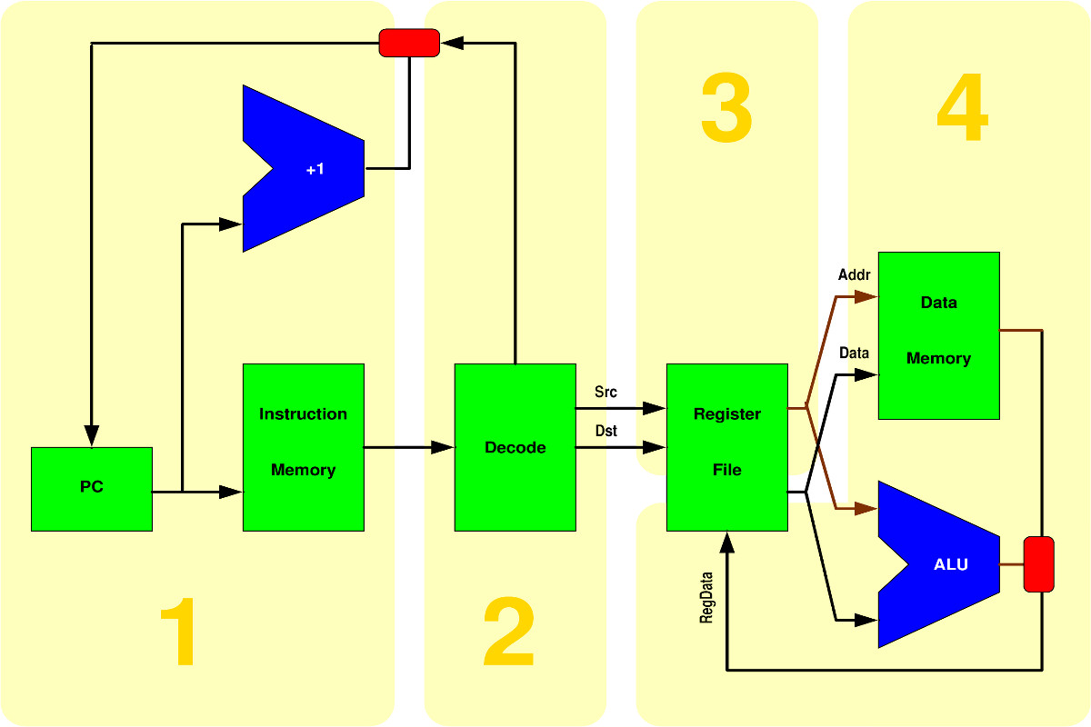
I could ask you to design your own single-cycle implementation
from scratch, but I'll save us all some time and give you an
overview diagram for such a thing right here. You are not
required to use the following, but let's start thinking with:
Of course, that leaves out a lot of details... and even then
you're not yet ready to start writing Verilog code: design
first, code second.
Setting The Stage(s)
One of the first steps in making a pipelined implementation is
figuring-out how many stages there should be and what belongs in
each.
It is fairly obvious that the memories (including the register
file) will take a little while to access, and we all know ALUs
are notoriously slow. Thus, we'd expect a stage for each of
those things along any circuit path. However, there is also
that funny little issue of decoding the register references from
each stack instruction, and that's probably worthy of its own
stage. That probably gives you at least the four stages shown
above in yellow.
So, what else should you be thinking about?
-
There's a little concept I like to call Owner
Computes. Basically, the idea is that multiple
potentially simultaneous writers to an object (register) is a
problem, so let's have a single entity responsible for updating
each writable object. We'll call that thing the owner. A thing
here would either be a module or at least an always
block (and you probably at least want an always block for each
pipe stage). For example, the PC shouldn't be stored into by
multiple stages even though you might be in very different
stages when you determine to update it by adding 1 vs. jumping
to a target address. Pick one stage to store new values into the
PC and let it look at (read) things set by other stages to
determine which value should be stored into the PC. The same is
true of the register file; it should be owned by what was called
stage 4 in the above diagram.
-
At various times in EE380 and EE480, we've mentioned that most
modern processors don't literally execute the instruction set
seen by the programmer, but translate it into something more
convenient to execute. Well, that's what stage 2 in the above
diagram is doing. In effect, you're defining an internal
instruction set... and it's probably good for you to be aware
that you are doing that, and to document any significant aspects
of the internal instruction set that aren't obvious from the SIK
documents you've been given in the assignments.
-
You're probably thinking that the multithreading is going to cause
problems. Well, not really. However, your fetch logic needs to flip
back and forth between the threads with each clock cycle.
You might be tempted to design the processor without mutithreading
and then add it, but don't. Multithreading makes this design easier.
Think about it. Enough said. (Well, almost enough -- also be careful
that you don't update the wrong PC, etc.)
-
One of the little details in multithreaded pipelining is how you
decide which thread gets to go next. Like Intel's
hyperthreading, you only have two threads -- so it's obviously
alternating when both have work to do. As I've stated in class,
the folks at Intel seemed to think it was fine to literally do
odd/even clock cycle scheduling: thread 0 fetches an instruction
in even clock cycles, and thread 1 in odd cycles. However,
various Intel processors never stray from that even/odd
pattern even if one thread isn't ready to fetch during its turn;
it will not fetch in that cycle rather than run the thread that
was ready. It would be desirable to let the thread that isn't
blocked use every cycle, but they don't do that. I'll leave it
up to you to decide how you pick which thread gets to fetch an
instruction during each clock cycle, but I'll repeat my little
in-class comment that Intel has some pretty smart engineers....
-
Ignoring multithreading, there can be register dependences at
the register read stage: you can either implement value
forwarding or interlock to resolve dependences, but
fundamentally it is most desirable to avoid blocking the entire
pipe because of a dependence in just one of the two threads. The
catch is that this seems difficult to implement, because it
would require allowing two instructions, one from each thread,
to simultaneously be in the register read cycle. Thus, for this
project, it is permissible that a register dependence blocks
the entire pipe at the register read stage, not just the thread
it occurs within. However, the most interesting
observation is that, if you use a 4-stage design like that
suggested in the diagram, multithreading can make the entire
register dependence problem disappear. Why? With a
strictly odd/even thread scheduler, by the time an instruction
from one thread is in stage 3, the instruction before it in that
thread has already completed execution... so there is nothing
left to wait for! Don't forget that the registers used by each
thread are inherently independent of those used by the other
thread.
-
As soon as you see that there are conditional jump instructions,
JumpF and JumpT, you should immediately be
thinking about how to handle fetching the next instruction.
Thankfully, they're jumps and not branches, so you don't need to
run through an adder to compute the target address. However, to
know if the jump is taken or not, you need to know how
torf is set. The setting of the torf bit can
happen arbitrarily far ahead of time -- if the compiler or
assembler code it that way. However, it is very likely that the
instruction that sets torf is a Test
instruction right in front of the JumpF or
JumpT. My diagram above makes it look like the address
for the jump target and the torf flag come from stage
2, but I'll tell you right now that they don't; I want you to
think about where they come from. Given that torf might
not be set until later in the pipe, you have the classic choice
of how to handle this: stall until torf is ready or
speculatively fetch instructions and squash them if it turns out
that your taken/not-taken guess was wrong. However, again
remember that you are implementing a multithreaded processor:
if you decide to stall, that stall should only block instruction
fetch for that thread. The next clock cycle, the other
thread can still fetch. Thus, blocking really would need to be
implemented by pretending to fetch a NOP. However, think about
what you're doing here -- if you're careful about your pipeline
design, multithreading can make this problem a lot easier to
solve.
In lectures you got a fairly detailed overview of how to go
about designing hardware for a complete computer system. The
bottom line is that you should start by defining the set of
function units, data paths, and control signals you will need.
Define the interfaces and signals. Then build the modules
themselves. Note also that for this project, you are
allowed to use things like the Verilog + operator to
build an adder: you need synthesizable Verilog, but you
don't have to specify things at any particular level. You are
also free to use earlier project work from any of your team
members, or the sample solutions for previous projects, as
resources in creating this project; if you reuse significant
portions, be sure to state that in your implementor's notes.
My sample solution for the previous project, as was
presented in class, is the following AIK specification and Verilog code.
Let's be completely clear about what I expect: your submission
should be a viable four-or-more-stage, two-threaded, pipelined
Verilog implementation of the SIK instruction set. For this
project, I expect you to treat the instruction memory and data
memory as able to sustain one access each per clock cycle; it is
up to you if you treat them as a unified memory or as
Harvard-style separate instruction and data memories. Of
course, all significant design decisions made should be
discussed in your Implementor's Notes.
Test Plan
Yes, you still need one. Your project needs to include a test
plan (best described in your Implementor's Notes) as well as a
testbench implementing the planned test procedure.
I strongly recommend writing a test program that tells you what
failed by where it halts... but keep in mind that you will be
running two threads interleaved. Thus, you'll need to have some
way to intialize the two PCs, and you'll need the code for both
programs loaded into memory somewhere. Despite that, the Verilog
portion of your testbench can be something very simple, like:
module testbench;
reg reset = 0;
reg clk = 0;
wire halted;
processor PE(halted, reset, clk);
initial begin
  $dumpfile;
  $dumpvars(0, PE);
  #10 reset = 1;
  #10 reset = 0;
  while (!halted) begin
    #10 clk = 1;
    #10 clk = 0;
  end
  $finish;
end
endmodule
This just enables trace generation, intializes everything with a
reset, and then keeps toggling the clk until
the processor says it has reached a halted state.
Note that my online Verilog WWW interface allows use of
$readmem directives, so it is much simpler to use that
mechanism to initialize memory for your test cases. Include any
such files in your submission as files with names ending in
.vmem (to indicate that they are Verilog memory
initialization files).
Due Dates
The recommended due date for this assignment is before
class, Wednesday, April 5, 2017. However, the
submission window will close when class begins on Monday, April
10, 2017. You may submit as many times as you wish, but only
the last submission that you make before class begins on Monday,
April 10, 2017 will be counted toward your course grade.
Note that you can ensure that you get at least half credit for
this project by simply submitting a tar of an "implementor's
notes" document explaining that your project doesn't work
because you have not done it yet. Given that, perhaps you
should start by immediately making and submitting your
implementor's notes document? (I would!)
Submission Procedure
You should submit a tarball (i.e., a file with the name ending
in .tar or .tgz) that contains all things
relevant to your work on the project. Minimally, the tarball
should include the Verilog and AIK source code for the project
and a semi-formal "implementors notes"
document as a PDF named notes.pdf.
It also may include test cases (e.g., source SIK code and .VMEM
files), sample output, a make file, etc., but should not include
any files that are built by your Makefile (e.g., no binary
executables). Be sure to make it obvious which files are which;
for example, if the Verilog source file isn't
sik.v or the AIK file isn't
sik.aik, you should be saying where
these things are in your implementor's notes.
Submit your tarball below. The file can be
either an ordinary .tar file created using tar cvf
file.tar yourprojectfiles or a compressed
.tgz file file created using tar zcvf
file.tgz yourprojectfiles. Be careful
about using * as a shorthand in listing
yourprojectfiles on the command line, because
if the output tar file is listed in the expansion, the result
can be an infinite file (which is not ok).
 Advanced Computer Architecture.